I'm currently in the process of populating the WaterFeeler3 main board. Still waiting for a few components from China (ran out of relais and still missing the screw connectors), but it's ready enough to start tinkering with the basic system software.
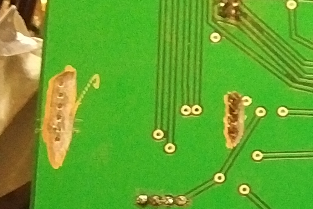
As i wrote before, the mainboard was manufactured by PCBWay in China according to my design files. I'm very happy with the quality of the board. There were to design flaws in my part. One was a wrong connection to one of the voltage regulators (my bad entirely). The other one was a design error for the real-time clock module, which connects all all pins to the ground plane on the backside layer - i should have checked after downloading the part, but i didn't.
Both times, i was able to solve the problem with a bit of dremmeling and then hand wiring the correct connection(s). PCBWay makes the PCBs sturdy enough for that kind of abuse.
This is the front side:

And here is the backside:

Detailed look at the main dremmel rework:
Originally, i was planning on re-using many of the WaterFeeler2 components. But i decided mostly against it, i want to preserve WaterFeeler2 mostly as is for my personal collection. i'll remove the battery and solar charger (to prevent acid leakage), but leave the rest of the probes innards intact. The solar panel will get reused, though, since it's by far the most expensive component.
The new WaterFeeler3 will get a new custom housing. SInce i'm doing that and i'm using carbon fiber heater wire (floor heater wire), i'm currently debating if i want to fill the floor of the probe housing with concrete. It would make the probe a lot heavier, but just like in a house, the concrete would provice a very good thermal buffer. Which in turn would mean much fewer on/off cycles for the relais and also possibly better passive thermal stability during the day/night cycle in warmer months.
I'm also thinking of fitting the probe with FAST CORE style insulation plus an outer layer of thermal blankets (heat rejecting side outside). Cooling in summer months would be achieved by a small 5V or 12V fan, maybe even with a servo controlled shutter of the inlet/outlet ducts. This would allow cooling in summer, but somewhat efficient use of the survival heater with the limited power available.
So why a "survival heater"? While i'm planning to coat most of the electronics in some kind of transparent coating (probably just some cheap spray on paint), it's pretty much impossible to coat everything. I don't have any fear for the exposed DHT (digital temperature and humidity) sensors, they have been proven to survive my abuse just fine. But the raspberry camera and the servos obviously can't be treated the same way. It would ruin the camera image. And the most vulnerable part of servos for water intrusion is the bearing around the axle - coating that would stick the servos to a single position, making the useless.
Another vulnerable part if the valve of the water collection system experiment, which will also need heating and will therefore (most likely) also be inside the insulated enclosure.
The project is a few months away from completion at this point. Sourcing the parts cheaply is the most time consuming part of building a probe like this. Soldering up a board (after i have all the parts), writing the software and running the tests can all be done inside a week if i feel motivated enough.
Especially the software side, since i now have lots of the base software from previous missions and only need to adapt and enhance for WaterFeeler3. But even here, i'm going deliberately slowly. My most important goal is to make sure i can remotely update the software reliably, to fix any non-critical bugs that might slip through all my testing. As a side note, the in-the-field upgrade capability may not be implemented in some of the future missions - mostly, because those damn Arduinos only have a single serial bus, and i'll need that for the RS485 multi-arduino communication. I might have a way of circumventing that by using an intelligent switching board instead of using RS485, but this is still in the very early design phases.
The one major software improvement WaterFeeler3 and all future missions based on the same board will have is scheduled commands (if the RTC board works, that is). The real time clock provides accurate time and also a 32kB I2C EEPROM. I'm currently planning on having 4 days of scheduled commands in memory, that would give me 256 timed commands per day, which is more than enough. To simplify things, the EEPROM will store standard DGN packets minus checksums (28 byte) plus a start time in seconds. This way, the scheduler only has to copy the "data packet" from EEPROM to the receive-buffer at the correct time and re-calculate the checksums. The rest of the code will work under the assumption that it just received a new command from mission control and act on this. Doing it this way minimizes "special handling" code and can re-use all the already implemented command code.
In theory, day 4 may include a request to mission control for a new sequence. Or it might start up the Raspberry Pi (PanCam) and ask for an update. If there is no update, the probe will just roll over to day 1 of its sequence.
Those time-based stored procedures will enable to automate complex sequences of events, like booting the PanCam, taking an image, downlinking a low-res version via SSTV and then shut down PanCam again. During winter, this can even be combined with switching to and from low power mode.
I'm even thinking of using special sequences during the comissioning phase (first 4 days of the mission). This could include doing an automated engineering, science and imaging sequence including downloads, in case there is an uplink problem. This four days sequence might even include automatic steps to change the radio frequency unless cancelled - basically, if the uplink doesn't work, the probe would switch to another radio frequency on day 2, then again on day 3 and day 4, to try to find one that works. There is not much i can do if downlink from the probe is broken, but if its only an uplink problem (similar to a problem i saw on one of my GEO sats last year), this would allow me to run at least a very basic mission for a few weeks or months, with the probe cycling through a 4 day mission plan.
But that's all a bit in the future. For now, i'm just glad the the magic smoke didn't escape when i turned the power on for the first time. More updates will follow in the next few days. |
