You might have seen my Youtube video on future missions:
This blog post is a short status update for this.
Relay2
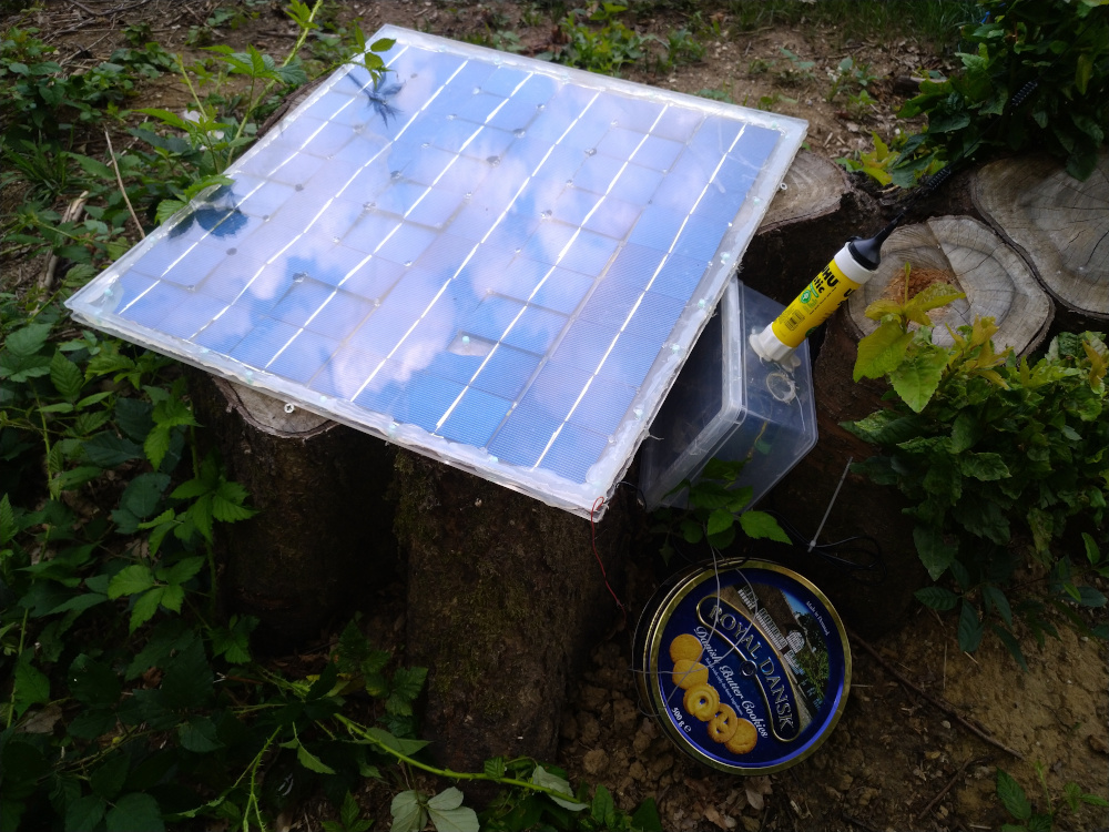
Relay2 (the second one designed, the first one to go live) is working just fine, as expected. It's powered by Solstice, so i didn't expect any power problems there. Despite the flimsy construction, it survived a week of very bad weather (storms, thunderstorms, hail) just fine.
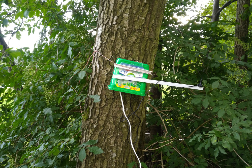
Relay1
I also managed to cobble Relay1 together from the parts shown in the video. I was expecting to have to fix a lot of problems, but everything except the real time clock scheduler interrupt worked absolutely fine, so i basically forgot to post about it.
As you can see, this is the most professional antenna mount i have ever designed. Uhm, ok, i needed the raise the antenna a bit from the box and i have a ton of empty glue sticks around. I go through them like crazy for my 3D printing stuff. A bit of hot glue and it turned into an antenna mount. But hey, it works.
The broken RTC interrupt is a bit sad, because i was hoping i could test some of the clock based power saving features. But frankly, this is not an unexpected failure. Both Relay1 and Relay2 are using the old Radioduino 1 hardware, which was designed as a prototype/proof of concept with daughterboards flopping in the wind (and never meant to work in a real project).
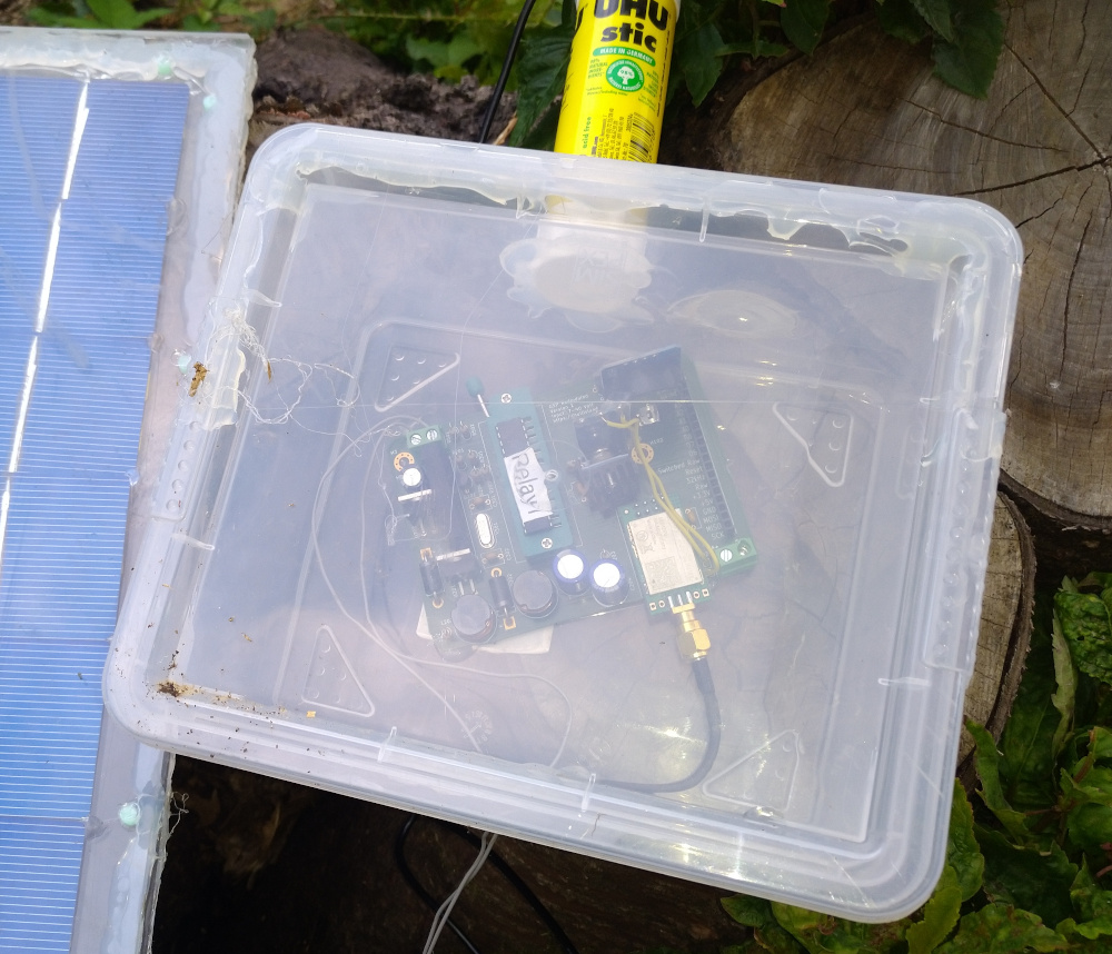
So far, the cobbled together "it's nearly a real solar charger" circuit with the questionable "least expensive sort-of-battery-managment-system board i could find on Ebay" is working just fine.
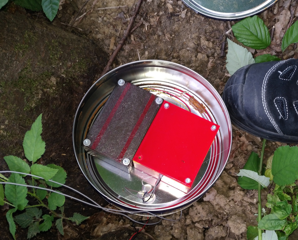
The two 18650 batteries are in the grey box with the red striped. The red box houses the electronics.
And before you as, yes, that is a metal cookie box. I needed something fireproof, i like cookies and my favourite ones come in a metal can.
Trailblazer
Before starting the Rover project (which might or might not happen this year after all), i wanted to do a practical test of my Radioduino 2 hardware. Both to develop and test all the required software and also to find ways to improve the Radioduino hardware itself.
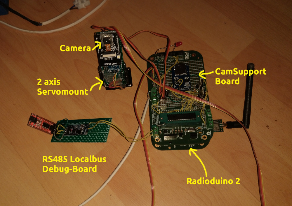
Trailblazer will be a static probe. I haven't decided yet if it will be powered by Solstice (most likely) or if it will be a standalone system like Relay2. Trailblazer will feature a single camera that can take images in two different resolutions:
320x240 with a somewhat-real-color color channel compression. This will be used for the low resolution NavCam (navigation camera) images on the rover project
1024x768 full color to simulate images taken by the PanCam (panoramic camera) of the rover
The camera is mounted on a 2 axis servo motor thingy i got from Ebay a couple of years ago. All the data processing is handled by the CamSupport (camera support) board that can also control two external lights for night photography.
Trailblazer uses RS485 to communicate between the subsystems. It's not ModBus but my own, simpler "LocalBus" protocol. Mostly because it found it easier to write my own protocol then to continue debugging third-party ModBus libraries.
This project is still in somewhat early development. The hardware all works, but i'm still have a few battles with the software side of things. Let's just say that every board has working software, and they can communicate with each other. But i still have to fix cases where one or two of the boards suddenly decide to ignore messages or sends the entirely wrong reply. You know, typical software development stuff.
Radioduino 3
I already have some "lessons learned" for Version 3 of Radioduino and i'm in the verly early stages of developing the hardware changes and learning the required skills to pull it off. Here are some of the things i want to change:
Instead of stacking the boards, have all the interboard connectors on one small side. Use an interconnect board (like a PC mainboard, but without much electronics, just connectors) where all the boards slot in.
Change the Radioduino processor to an Atmega 2560 for more Serial lines, lots more flash memory and more interrupt pins
Use the 2560 to support local debugging via Serial, plus Localbus AND Modbus
Increase amount of byte-accesible external EEPROM to at least one Megabyte
Move power supply to seperate board, add more switchable power channels (controlled via designated IO lines on the interconnect board)
Add SD Card storage to the main Radioduino board (in addition to the EEPROM increase)
Add Open Drain interrupt lines between boards
Add dedicated 12V regulator, powered from the raw input, on the power board, to provide power to 12V devices like car headlights (those are quite cheap on Ebay and provide lots of light)
Design some low power external watchdog circuit that can work on the scale of hours or days, independant of the real time clock to support deep sleep cycles, while making sure we wake up even if the RTC fails